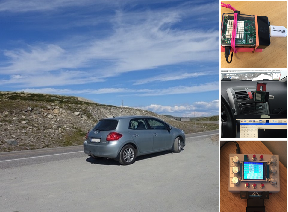
Previously I wrote a blog about how to measure hamster via IoT wheel. This reminds me another personal project I did back to the winter of 2018/2019, for measuring car performance.
Other articles in this series:
- Part 1 (this article):
Talk about the hardware/software running on the edge (the car) for collecting data. - Part 2: Talk about how to get insight from the data with different analytic tools.
1. Overview on the edge
1.1 Hardware
- OBD2 USB connector
OBD2 is an interface/protocol that is available for 1996 and newer vehicles. It reports various telemetries of the vehicle. - USB GPS dongle
For collecting location information - Raspberry Pi
Running Linux, Azure IoT Edge runtime and hosting 2 modules (OBD and GPS location) - USB Wifi dongle
For connecting mobile phone hotspot - Mobile phone
For realtime data uploading to the cloud via 4G - Power bank (optional)
For powering up raspberry pi. Alternatively, you can use a 12V->5V adapter to use the car battery.
1.2 Software
- Azure IoT Edge
- Docker
- Python
1.3 Dataflow and Architecture

2. Developing IoT Edge modules
2.1 Introduction
2.1.1 Design Principles
As there are many possible situations can happen on the edge, such as disconnection from OBD2 connector, or loss of GPS signal (when going through an underground tunnel), the modules are built with the following principles:
- Design for failure
- Auto healing
In addition, the modules are built into docker containers, together with Azure IoT Edge runtime, which makes it easier to deploy.
2.1.2 Source code
All source code can be found at https://github.com/linkcd/IoTCar
2.1.3 Sample data
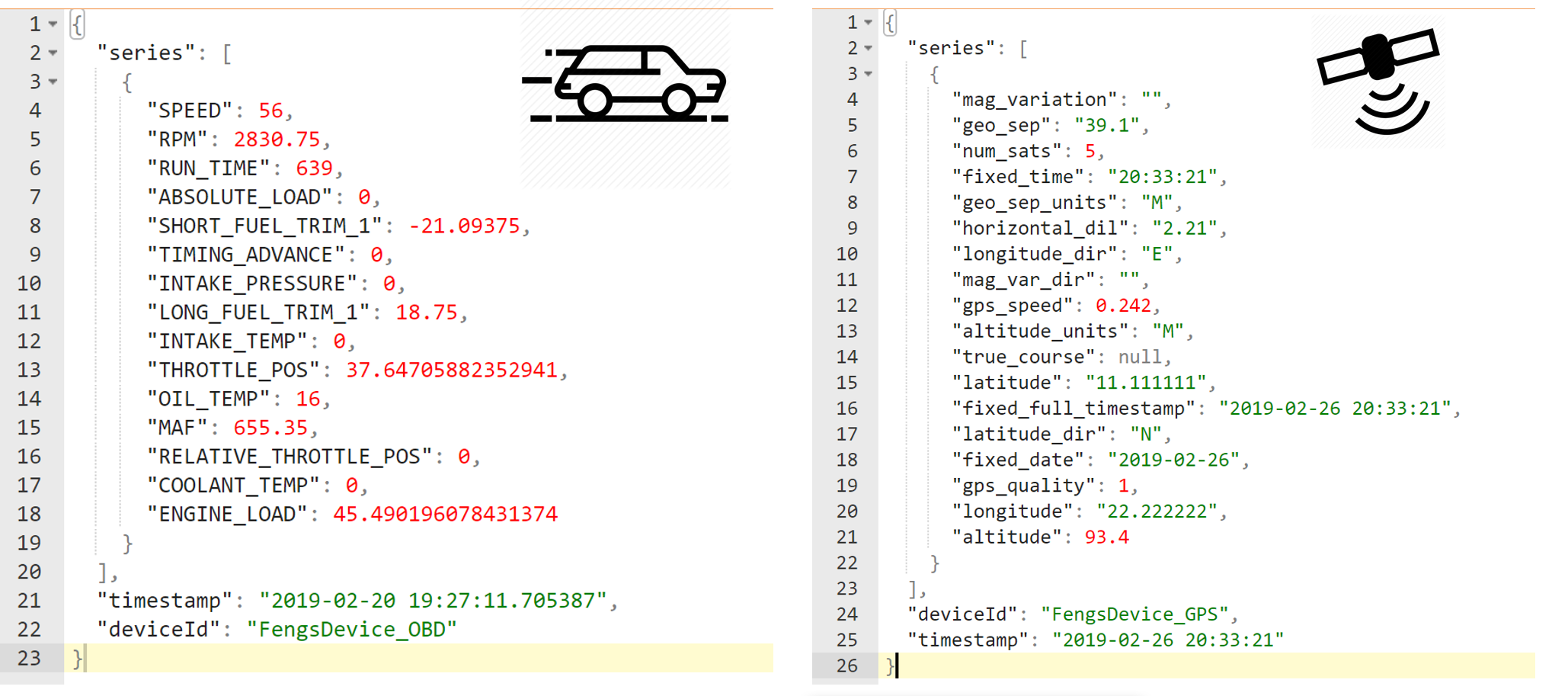
This edge device (raspberry pi + OBD connector + GPS dongle) reports the following data per second:
2.2 GPS location module - details
With a USB GPS dongle, it is quite easy to get the location information by using tools such as GPSD.
2.2.1 You have to dev/test in the field, not only in the office
I immediately met the first challenge: The USB GPS dongle requires a good open sky view to work well. The one that I used does not have an antenna, so I need to put the whole thing (raspberry pi + GPS dongle) outside of the building (or at least outside of the window).
Remind you that it was winter in Norway during that time, and I was not a fan of typing keyboard in the snow with -5 degrees.
Firstly, I have tried do this in my car: parked the car in an outdoor parking slot, put the raspberry pi on the dashboard and remote desktop to it. Well, it worked, GSP signal was strong, but it was quite difficult to type any keys behind the steering wheel :)
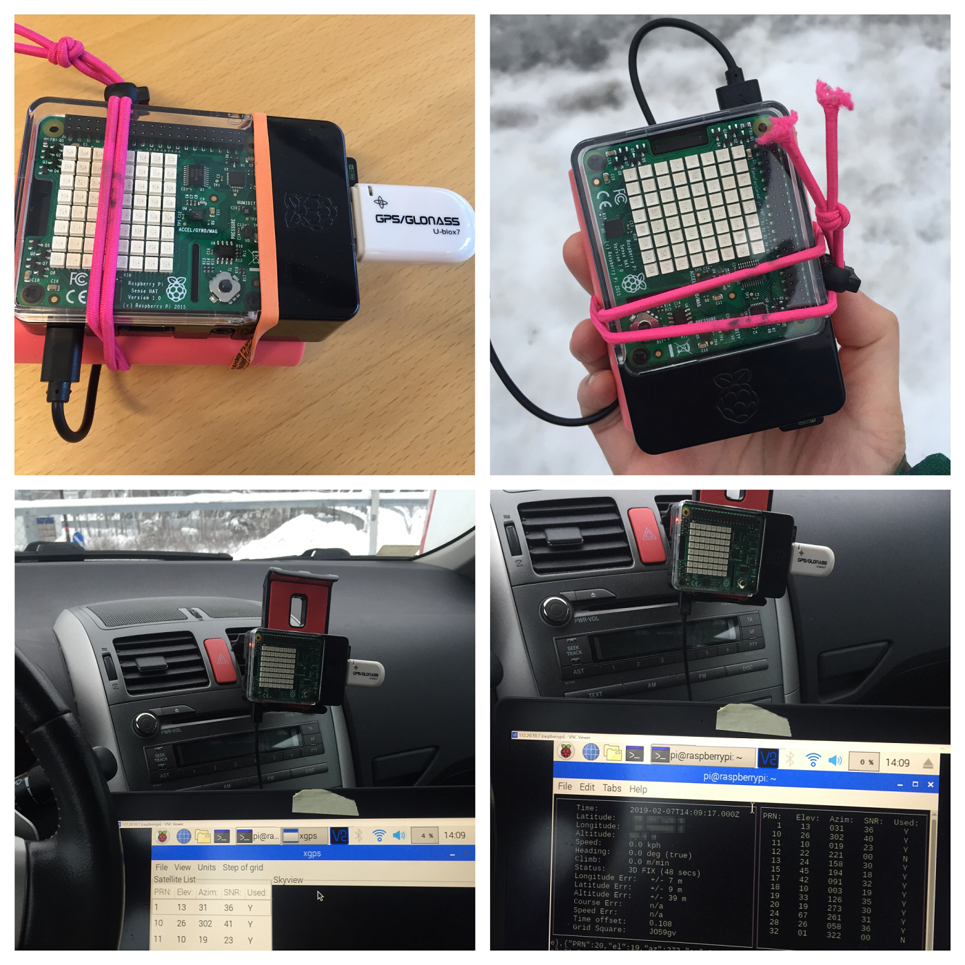
But soon I figured out a better solution on my balcony (see below picture), and that worked perfectly (as far as the wifi signal is good and the power bank battery did not die from the low temperature)

Now I can work from a warm cozy place and deal with the GPS data that is collected from the “cold box”.
2.2.2 Working with GPS data with python
The GPS receiver reports data as NMEA sentences, and we are combining GGA and RMC.
1 | # GGA |
Here we are using a python lib pynmea2 for handling the NMEA sentences, the detailed logic can be found at source code here.
In addition, we need to do some small math for calculating the correct latitude and longitude, otherwise you will find your car was driving in the ocean :)
1 | # The latitude is formatted as DDMM.ffff and longitude is DDDMM.ffff where D is the degrees and M is minutes plus the fractional minutes. |
Finally, this module reports the following data per second
1 | { |
2.3 OBD2 module - details
2.3.1 You cannot do it in the field, do it on an emulator instead
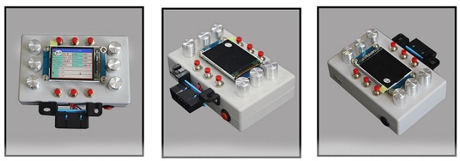
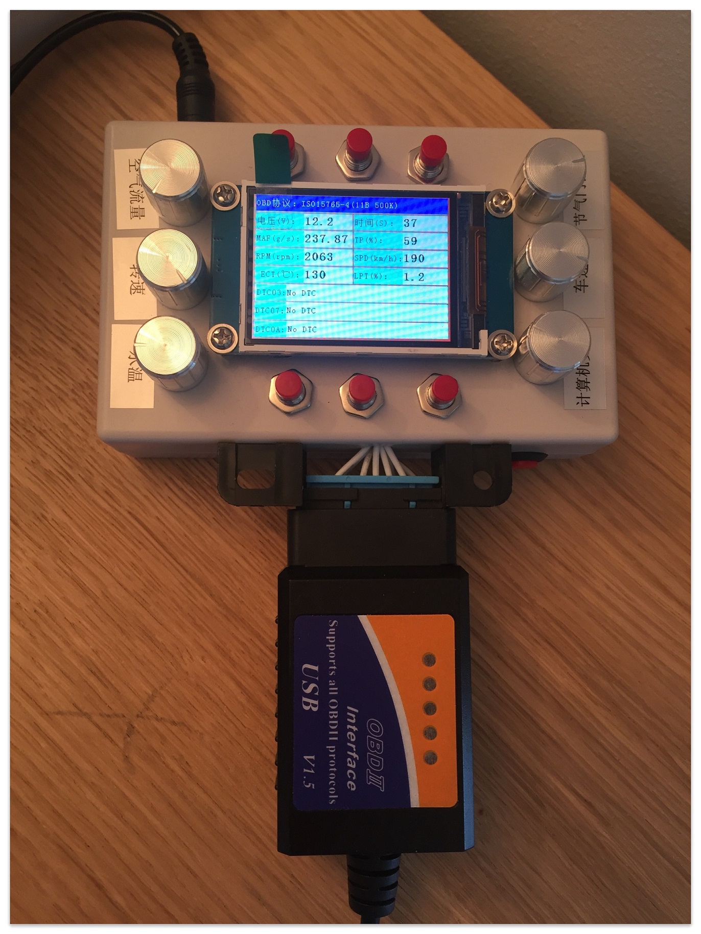
Programming/debugging OBD2 can be difficult - after all I do not want to be programming while driving. Instead of hiring a driver and typing the keyboard on the passenger seat, it is better to use an ODB emulator to emulate all telemetries (and error codes) of the car.
OBD2 Emulator
Lucky I am not alone who has the same problem during OBD development. There are professional and affordable emulators on Aliexpress and Taobao (BTW The price on Taobao is 1/3 as Aliexpress!). The detailed features can be found at [here](OBD emulator features.jpg). My respects to the designers of this emulator - you are life savers!
2.3.2 Design for failure and auto healing
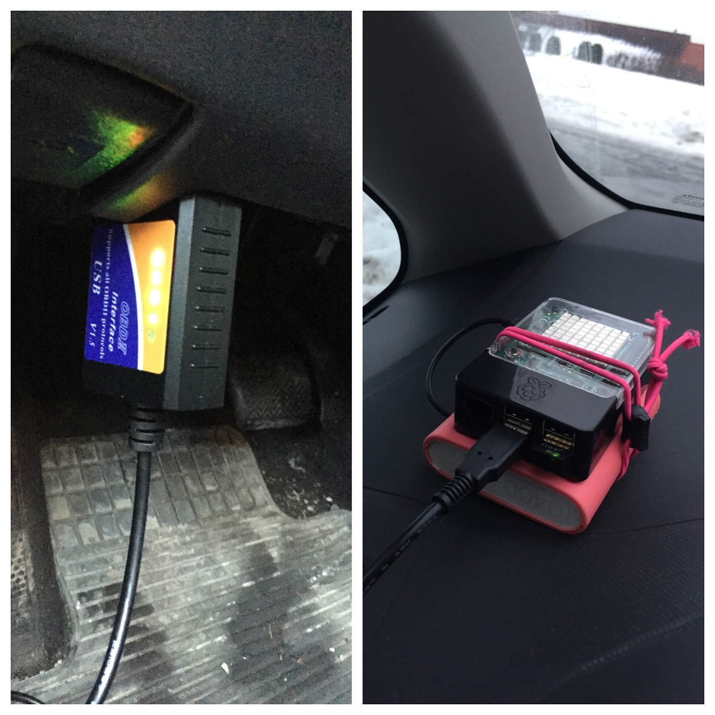
Now, with the emulator and python obd lib, it is easy to collect the telemetries of the car.
However, the library does not take care of failures and auto-healing, which we need to do it ourselves, otherwise the code just throw exceptions and stop working.
Thanks to the emulator, it is easy to test all corner scenarios, such as disconnect the ODB and reconnect while “the engine” is still running, in a safe environment. That is impossible to test/debug with real car.
The following code snippet ensures the modules works with different scenarios and self-healing:
- Car is powered off
- Car is powered on but engine is not started yet
- Engine starts
- Engine is stopped but car is still powered on
- OBD receiver is disconnected (e.g lost bluetooth signal)
1 | def getVehicleTelemtries(deviceId): |
Finally, this module reports the following data per second:
1 | { |
2.3.3 Tips: Considering use ‘Real Time Clock’ or RTC board for your Pi
As Raspberry PI does not have an RTC, the system clock was reset after each power-on. If it has an internet connection, it will fetch the correct date-time from internet, with some delay.
In the current logic, both GPS and OBD modules are using the system clock as the event timestamp. Therefore, if the Pi failed to have internet connection (happened often with mobile hotspot) or sending data before system clock is updated due to delay, the event timestamp will be incorrect.
To overcome this issue, you can install a RTC (Real Time Clock) to the Raspberry Pi, such as this and this.
I end up with a UPS-18650 Raspberry pi UPS Power Expansion Board With RTC. It comes with a power bank AND a built-in RTC. It is design and built by ACE design studio in China, and I am very happy about it. Definitely buy more from them next time.
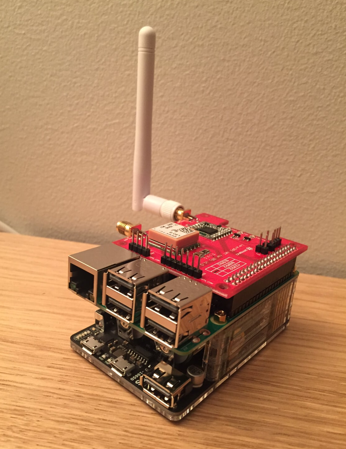
(Picture: My to-be-tested Raspberry Pi with UPS power expansion board and LoRa/GPS Hat.Hopefully it can use LoRa network connections to replace 4G)
3. Put things together and send to Azure
3.1 Config on the edge
Now we have 2 modules and we have built them into 2 docker images (in variables ${MODULES.OBDModule.arm32v7} and ${MODULES.LocatorModule.arm32v7}). I was hosting them in the dockerhub but it can also be hosted in any private registration.
For now we did not do any computing on the edge but simply forward them to Azure Iot Hub (see here)
1 | "$edgeHub": { |
More info can be found in the deployment.template.json.
3.2 Visualization in the cloud
Now we 2 module docker images running on the Raspberry Pi and sending data to Azure IoT Edge runtime. The Raspberry Pi has wifi connection to mobile phone 4G hotspot and forwarding the data to Azure IoT Hub in realtime.
With Azure IoT Hub and Azure Time Series Insights(TSI), we can now visualize the data:
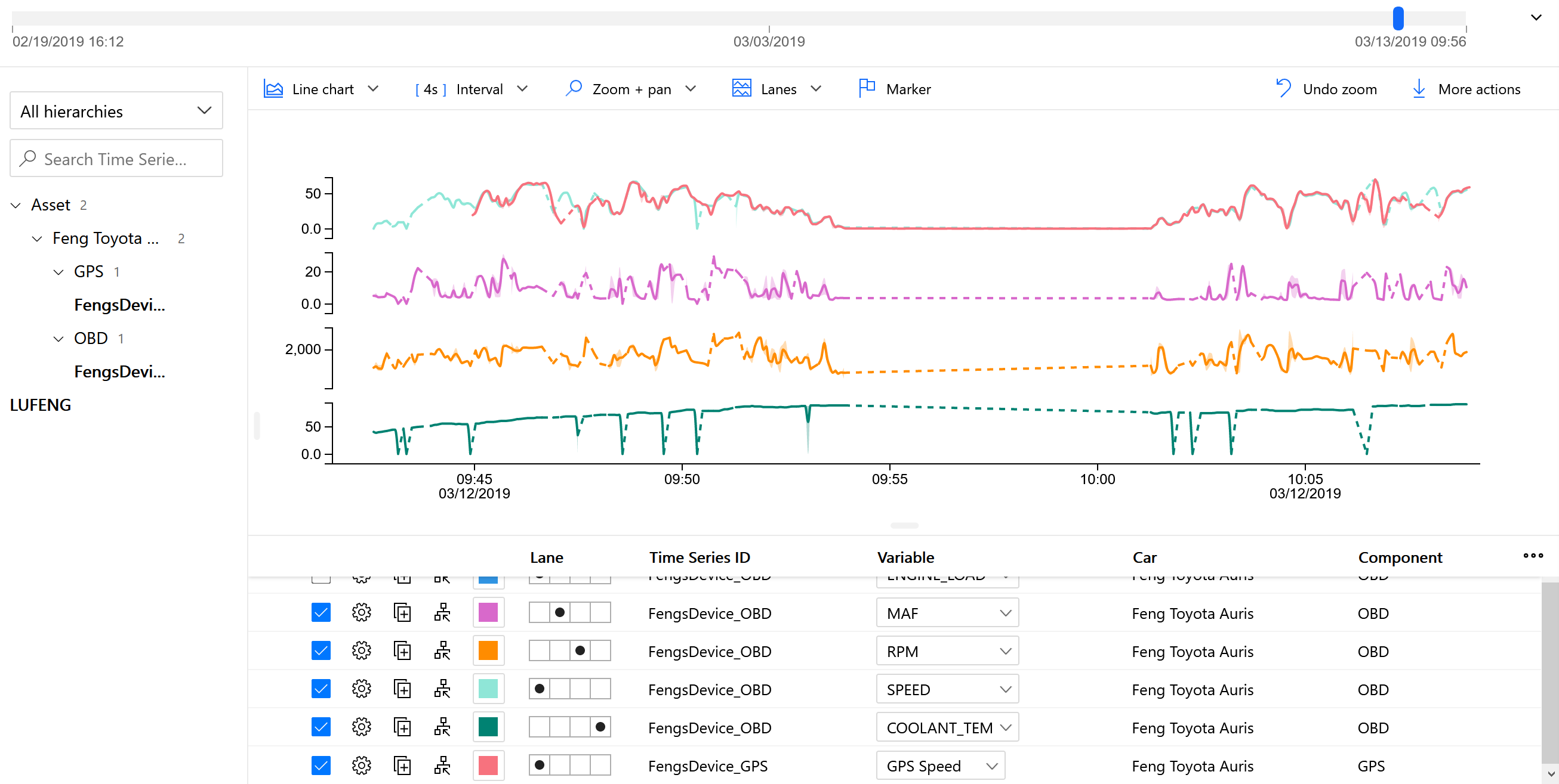
This is a quick example of data analytics for the IoT car. In the second part of the series, I will talk more about the data analytics part (including TSI, DataBrick ++) in the cloud.
Continue reading part 2